
AUTOMOTIVE / LINE COMPONENTS
Automotive line components.
Engine oil lines, coolant pipes and EGR corrugated assemblies built around the part drawing, installation envelope, interfaces and project-defined verification.
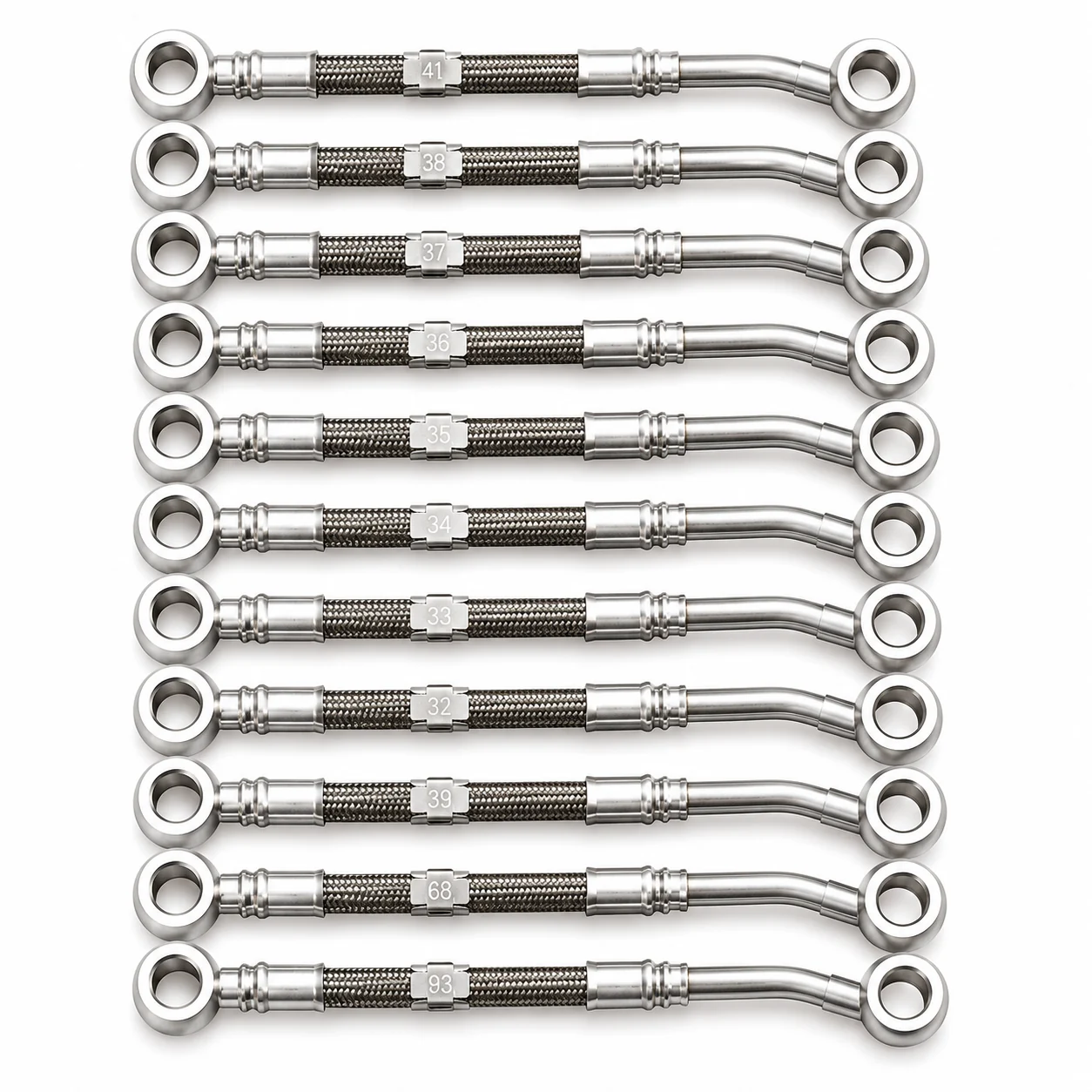
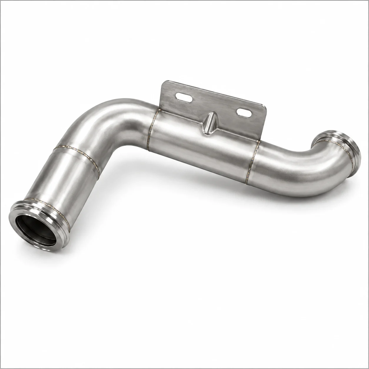
ROUTE
Installation geometry
ENDS
Connection interfaces
FLEX
Movement sections
DRAWING
Revision control
PRODUCT RANGE
Four component groups.
Each controlled by the drawing.
Images show representative forms. Vehicle platform, fluid circuit, material and acceptance criteria must be confirmed by part reference.
ENGINE OIL
Engine oil line assemblies
Flexible and formed sections reviewed as one routed assembly.
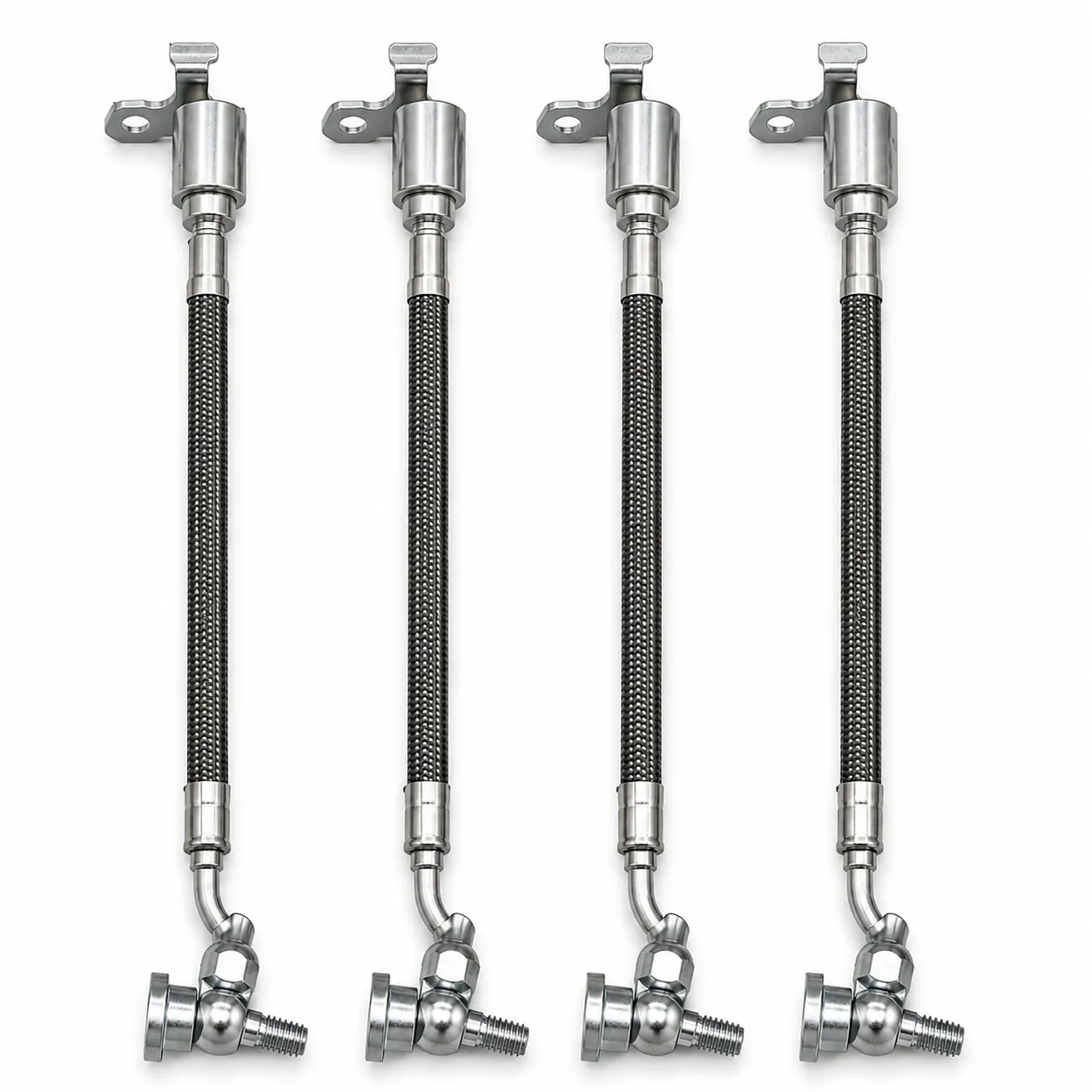
FLEXIBLE SECTION
Flexible oil-line sections
Hose construction, fittings and bracket positions are project-specific.
TERMINATED LINE
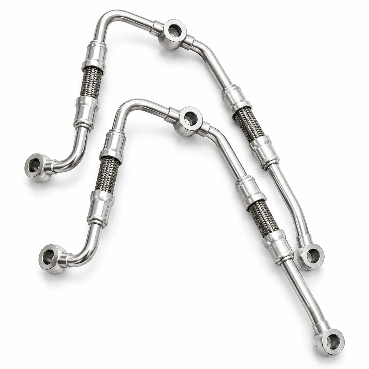
Terminated line components
Interface geometry and orientation require the controlled drawing.
ALUMINUM COOLANT
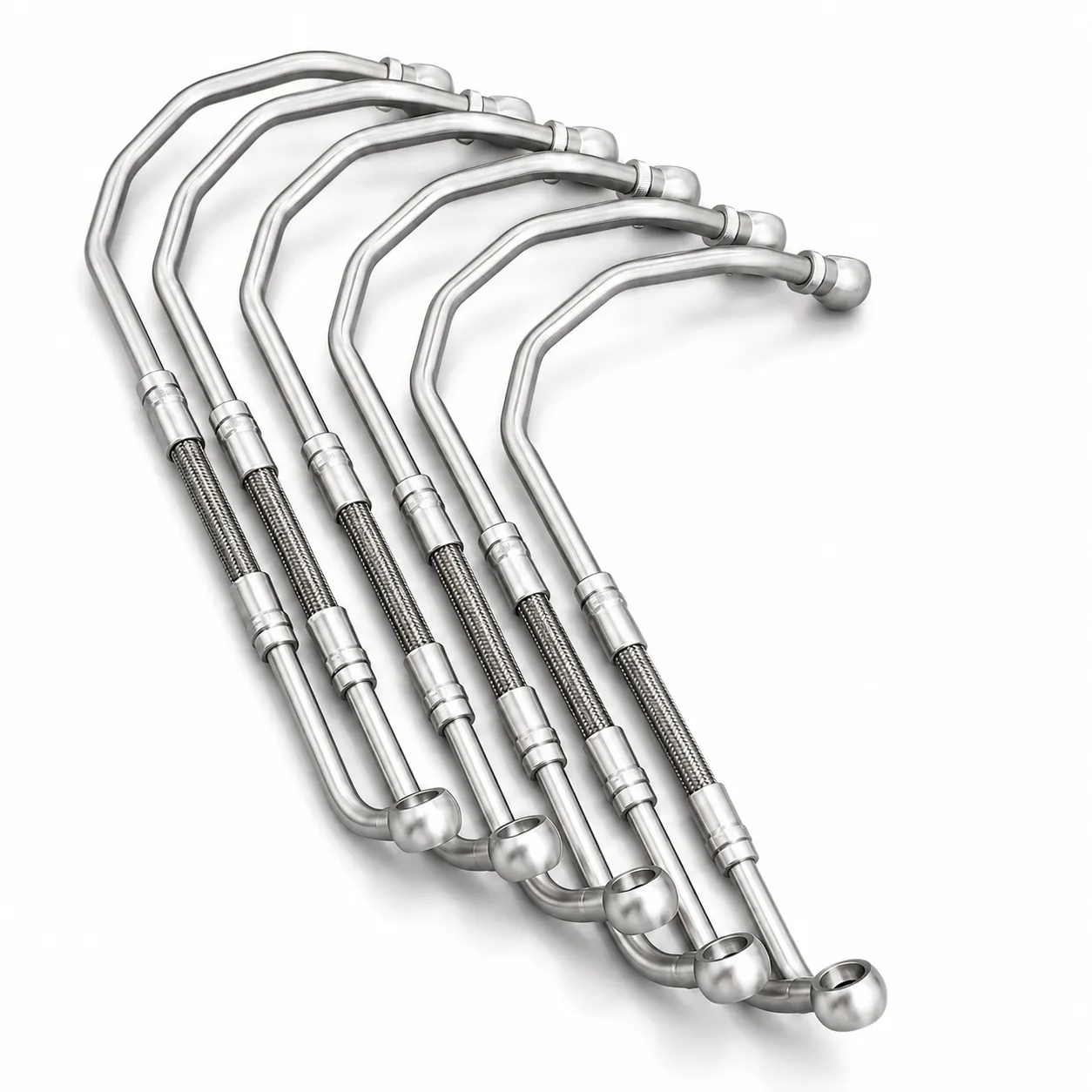
Aluminum coolant pipes
Formed aluminum routing with project-defined ends and brackets.
STAINLESS COOLANT
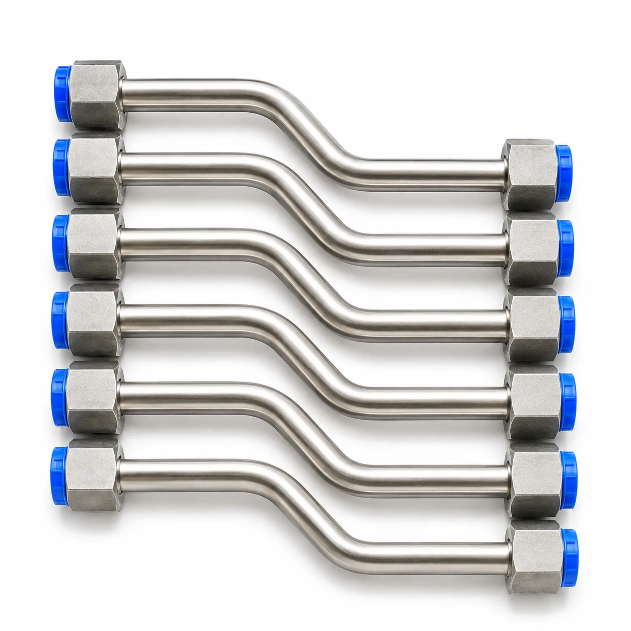
Stainless-steel coolant pipes
Material, wall, joints and acceptance requirements are confirmed per project.
FORMED ROUTING
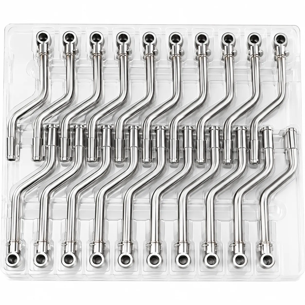
Formed coolant routing
Geometry and attachment points reviewed against the installation envelope.
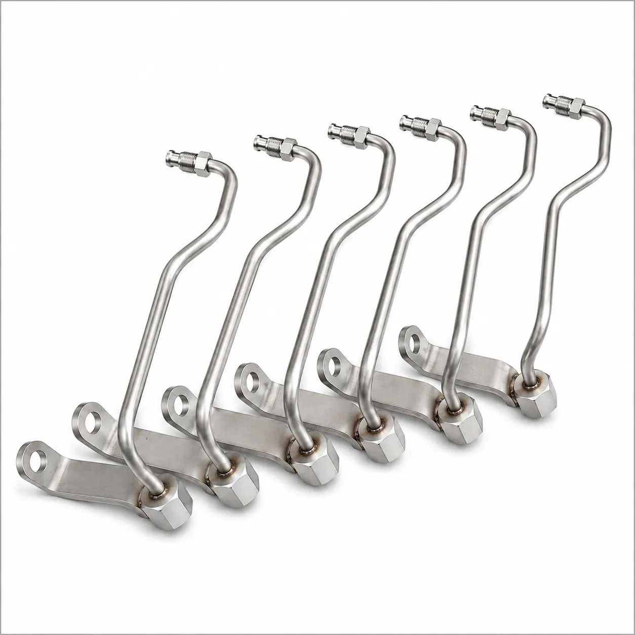
EGR FLEXIBLE
EGR corrugated assemblies
Bellows compensation integrated with formed tubes and interfaces.
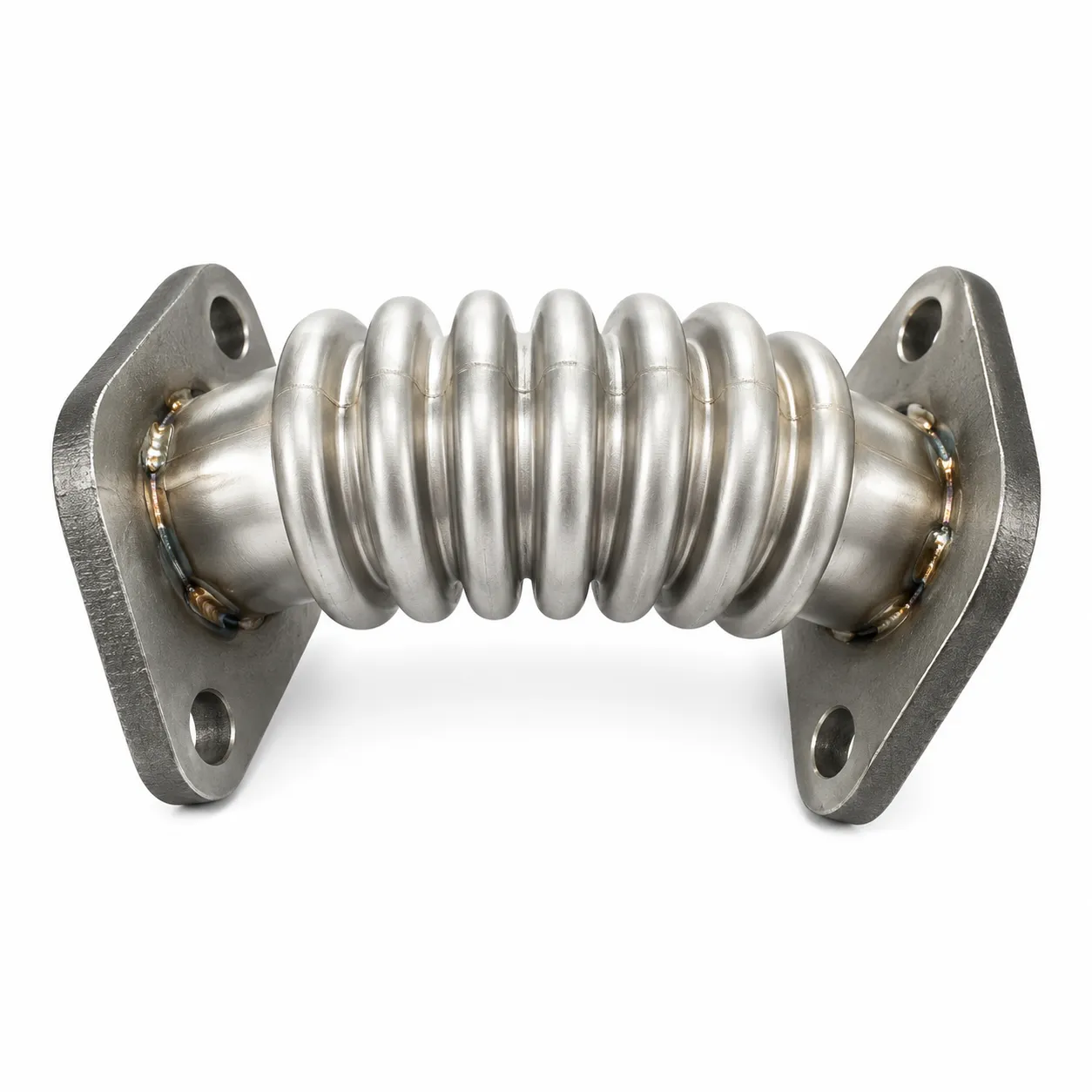
EGR FORMED
EGR formed components
Flange, bracket and weld locations are drawing-controlled.
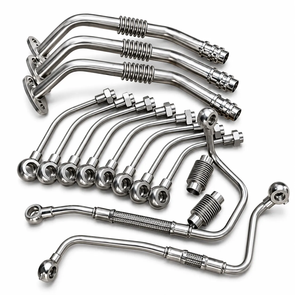
EGR / FLEXIBLE COMPENSATION
Temperature, vibration and geometry are reviewed together.
Do not select an EGR-style component by appearance alone. Share the gas path, temperature profile, displacement, mounting interfaces and drawing revision.
PROJECT WORKFLOW
From drawing to controlled delivery.
DRAWING-LED CONTROL
One continuous engineering path.
Geometry, service conditions and verification remain linked to the same drawing and project requirements throughout the review.
PART REVIEW
Routing and interfaces
Confirm connections, brackets, flexible sections and installation envelope.
DUTY DEFINITION
Fluid, heat and movement
State the media or gas, pressure, temperature and displacement.
VERIFICATION
Acceptance before production
Agree dimensions, acceptance criteria and required documents.
RELEASE
Revision-controlled delivery
Use the approved drawing, marking reference and packing requirement.
Have a drawing or existing sample?
Send the part reference, system use, installation envelope, connections, quantity and verification requirements.